STA
Static Timing Analysis (STA) checks that the design has no setup and hold violations. This is very important, and a failure here could cost you a respin of your ASIC. It is a way of verifying timing quickly without the complexity and time taken to find such issues using back-annotated digital (or even analogue) simulations. Setup violations imply that the circuit runs too slowly to work at the given clock rate, hold violations imply the circuit will fail at any clock speed.
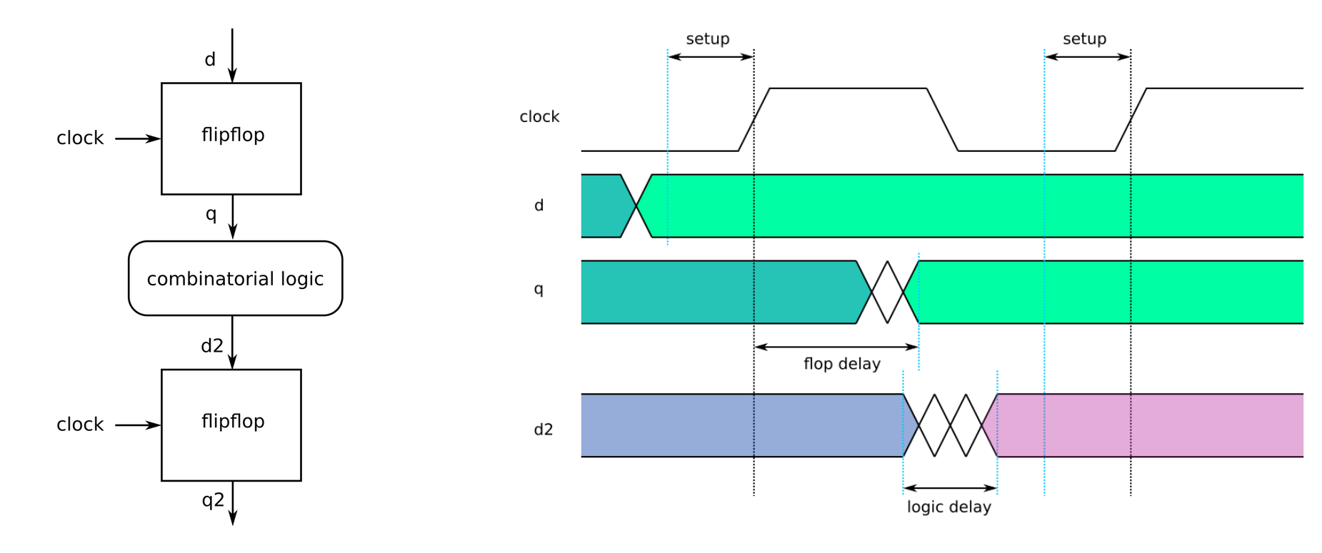
When the input clock rises, a flip-flop will capture and store the incoming data. An ideal flip-flop would sample data exactly on the rising clock and immediately have that data available on the output and be insensitive to the input value until the next rising clock edge.
Real flip-flops need the data to stay steady (setup time) for some time before the clock edge, and to stay steady for some time after it (hold time).
If we want to know how fast we can run some combinational logic in between 2 flops, we need to know that the flop delay + logic delay is less than the clock period - setup time. Setup time relates to 2 adjacent clock edges. If the path takes too long then the design will fail at this clock speed, but we may be able to fix it by slowing down the supplied clock.

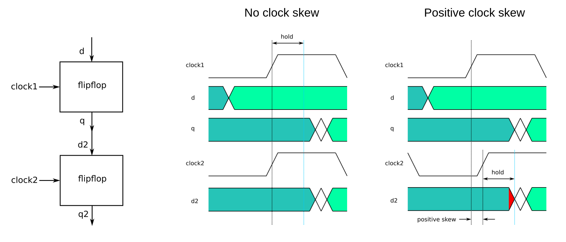
Hold time in comparison is related to a single clock edge. If we take the case where we put one flop’s output directly into another’s input (like in a shift register), then we need to make sure that the flops both receive the clock at the same time and that the second flop does not need the data to stay stable longer after the clock edge than the first flop delivers.

If the 2nd flop’s clock is slightly late for any reason, then we risk the data from the 1st flop changing in the hold time of the 2nd flop and hence the value for clock cycle 2 shoots through and overrides the value for clock cycle 1. If this occurs then the design will fail, and we cannot fix it by running the clock more slowly.
Google / Efabless / Skywater MPW1 hold problems
The first Google sponsored shuttle had severe hold problems that resulted in the RISCV core not working correctly. This was because the clock network had too much skew. The STA tool should have detected it, but it was misconfigured. Read more here.
Luckily we were able to find some work arounds, and I managed to get results from all my MPW1 designs.
OpenSTA
LibreLane uses a tool called OpenSTA. Its job is to find the fastest and slowest data paths in the design and to check that setup and hold timings are met. Typically we look for setup issues at the slowest process corner, and hold issues at the fastest process corner.
The required timing is set in the LibreLane config file. By default its 10ns, which means we are targetting a clock frequency of 100MHz. It can read the timing information about the standard cells and wiring from the PDK.
Min report - validating hold timing
To validate hold timing, OpenSTA does a ‘min’ timing analysis. Using the most optimisic timing values, how fast can new data arrive at the flip-flop after it receives a clock?
The report below is extracted from reports/synthesis/1-opensta.min.rpt which is created right after the synthesis step.
The report shows the shortest data path and sums the data arrival time (0.38ns). The data arrival time has to be more than the data required time (0.24ns). As 0.32ns > 0.24ns we pass the hold requirements.
Startpoint: _1786_ (rising edge-triggered flip-flop clocked by wb_clk_i)
Endpoint: _1787_ (rising edge-triggered flip-flop clocked by wb_clk_i)
Path Group: wb_clk_i
Path Type: min

Fanout     Cap    Slew   Delay    Time   Description
-----------------------------------------------------------------------------
                  0.15    0.00    0.00   clock wb_clk_i (rise edge)
                          0.00    0.00   clock network delay (ideal)
                  0.15    0.00    0.00 ^ _1786_/CLK (sky130_fd_sc_hd__dfxtp_2)
                  0.03    0.31    0.31 v _1786_/Q (sky130_fd_sc_hd__dfxtp_2)
     1    0.00                           rgb_mixer0.debounce2_b.button_hist[0] (net)
                  0.03    0.00    0.31 v _0894_/A (sky130_fd_sc_hd__inv_2)
                  0.04    0.04    0.35 ^ _0894_/Y (sky130_fd_sc_hd__inv_2)
     3    0.01                           _0216_ (net)
                  0.04    0.00    0.35 ^ _1177_/B (sky130_fd_sc_hd__nor2_2)
                  0.01    0.02    0.38 v _1177_/Y (sky130_fd_sc_hd__nor2_2)
     1    0.00                           _0030_ (net)
                  0.01    0.00    0.38 v _1787_/D (sky130_fd_sc_hd__dfxtp_2)
                                  0.38   data arrival time

                  0.15    0.00    0.00   clock wb_clk_i (rise edge)
                          0.00    0.00   clock network delay (ideal)
                          0.25    0.25   clock uncertainty
                          0.00    0.25   clock reconvergence pessimism
                                  0.25 ^ _1787_/CLK (sky130_fd_sc_hd__dfxtp_2)
                         -0.01    0.24   library hold time
                                  0.24   data required time
-----------------------------------------------------------------------------
                                  0.24   data required time
                                 -0.38   data arrival time
-----------------------------------------------------------------------------
                                  0.14   slack (MET)
Max report - validating setup timing
To validate setup timing, OpenSTA does a ‘max’ timing analysis. This uses the most pessimistic timing to check how long it takes the data to arrive at the flip-flop. It is measured against the next clock edge and verifies that the data will arrive in time.
For the max report, the longest path is found (2.14ns). This must be shorter than the data required time (0.88ns). You can see the library setup time incorporated in the calculation for required time below. In this case, the data isn’t ready in time, so we get a VIOLATED result.
Fanout is the number of gates attached to each signal, Cap is the capacitance (gate plus wiring), Slew is the edge rate, Delay is the delay of the cell, and the wiring (although here the wire delays are shown as zero), and Time is the accumulated time up to this point, relative to the original input clock edge. The ^ or v shows the edge is rising or falling.
Startpoint: _1474_ (rising edge-triggered flip-flop clocked by wb_clk_i)
Endpoint: _1452_ (rising edge-triggered flip-flop clocked by user_clock2)
Path Group: user_clock2
Path Type: max

Fanout     Cap    Slew   Delay    Time   Description
-----------------------------------------------------------------------------
                  0.15    0.00    0.00   clock wb_clk_i (rise edge)
                          0.00    0.00   clock network delay (ideal)
                  0.15    0.00    0.00 ^ _1474_/CLK (sky130_fd_sc_hd__dfxtp_2)
                  0.07    0.41    0.41 ^ _1474_/Q (sky130_fd_sc_hd__dfxtp_2)
     3    0.01                           mprj.wb_hp_glitch_en (net)
                  0.07    0.00    0.41 ^ _0723_/B1 (sky130_fd_sc_hd__a211oi_2)
                  0.06    0.05    0.46 v _0723_/Y (sky130_fd_sc_hd__a211oi_2)
     2    0.00                           _0137_ (net)
                  0.06    0.00    0.46 v _0730_/B (sky130_fd_sc_hd__or2_4)
                  0.06    0.27    0.73 v _0730_/X (sky130_fd_sc_hd__or2_4)
     3    0.01                           _0143_ (net)
                  0.06    0.00    0.73 v _0731_/B (sky130_fd_sc_hd__nor2_2)
                  0.15    0.16    0.89 ^ _0731_/Y (sky130_fd_sc_hd__nor2_2)
     3    0.01                           _0144_ (net)
                  0.15    0.00    0.89 ^ _0732_/B (sky130_fd_sc_hd__nand2_2)
                  0.06    0.10    0.99 v _0732_/Y (sky130_fd_sc_hd__nand2_2)
     3    0.01                           _0145_ (net)
                  0.06    0.00    0.99 v _0733_/B (sky130_fd_sc_hd__nor2_2)
                  0.15    0.16    1.15 ^ _0733_/Y (sky130_fd_sc_hd__nor2_2)
     3    0.01                           _0146_ (net)
                  0.15    0.00    1.15 ^ _0734_/B (sky130_fd_sc_hd__nand2_2)
                  0.05    0.09    1.24 v _0734_/Y (sky130_fd_sc_hd__nand2_2)
     3    0.01                           _0147_ (net)
                  0.05    0.00    1.24 v _0735_/B (sky130_fd_sc_hd__or2_2)
                  0.08    0.34    1.58 v _0735_/X (sky130_fd_sc_hd__or2_2)
     3    0.01                           _0148_ (net)
                  0.08    0.00    1.58 v _0736_/B (sky130_fd_sc_hd__nor2_2)
                  0.15    0.16    1.74 ^ _0736_/Y (sky130_fd_sc_hd__nor2_2)
     3    0.01                           _0149_ (net)
                  0.15    0.00    1.74 ^ _0737_/B (sky130_fd_sc_hd__nand2_2)
                  0.07    0.11    1.85 v _0737_/Y (sky130_fd_sc_hd__nand2_2)
     5    0.01                           _0150_ (net)
                  0.07    0.00    1.85 v _0744_/A2 (sky130_fd_sc_hd__o221a_2)
                  0.04    0.29    2.14 v _0744_/X (sky130_fd_sc_hd__o221a_2)
     1    0.00                           _0032_ (net)
                  0.04    0.00    2.14 v _1452_/D (sky130_fd_sc_hd__dfxtp_2)
                                  2.14   data arrival time

                  0.00    1.00    1.00   clock user_clock2 (rise edge)
                          0.00    1.00   clock network delay (ideal)
                          0.00    1.00   clock reconvergence pessimism
                                  1.00 ^ _1452_/CLK (sky130_fd_sc_hd__dfxtp_2)
                         -0.12    0.88   library setup time
                                  0.88   data required time
-----------------------------------------------------------------------------
                                  0.88   data required time
                                 -2.14   data arrival time
-----------------------------------------------------------------------------
                                 -1.26   slack (VIOLATED)
As it’s a setup violation, the design should still work at a slower clock.
Different reports
The reports are split into min and max files.
There are currently 5 calls to OpenSTA during a typical LibreLane including:
- In the synthesis exploration loop. Here the results can be used to iterate over different synthesis options to help meet timing requirements. For instance, if STA shows a path is too slow, then synthesis can use stronger cells to drive signals harder and faster.
- After resizing cells (to get better timing performance - see this video)
- After extraction. This is the most accurate timing report as it is done on the finished layout. These files are called:
- 23-spef_extraction_sta.min.rpt (numbering can change depending on LibreLane setup).
- 23-spef_extraction_sta.max.rpt
A clue could have alerted us to MPW1 issues
As mentioned above, MPW1 silicon was faulty because a hold time violation wasn’t detected. This was due to the tools being setup incorrectly. In fact you can see in the above timing charts that the clock network delay for both setup and hold timing reports was 0. This is a clue that the tool wasn’t working correctly, as there should always be some small delay in the clock network, particularly if wiring has been extracted.
Course feedback
The really exciting part for me is when you see what you've written actually end up as laid out digital logic.
Robert Baruch (digital course)